
Generator Probe Maintenance
Often when homogenization results change or efficiency decreases a key factor that impacted this was the maintenance and/or cleaning of the generator probe.
It is imperative that the probe be regularly taken apart and cleaned and wearing components like the lower bearing inspected.
Download our Generator Probe Quick Care Guide and review a full list of generator replacement parts available online.
Need more help?
Click here to request return paperwork for your homogenizer and/or generator.
Additional tips to maximize your PRO Generator Probe's performance.
Never run the generator assembly dry.
The generator requires a liquid sample/medium to lubricate the bearings during processing. If dry sample processing is needed, please contact a PRO Scientific representative to discuss using alternate materials for your lower bearing. Without the liquid, the PTFE bearings can burn out and cause damage to the generator itself.
Faster isn't always better.
Always begin homogenizing at a low rpm, and then gradually increase the speed to your target level. Running too fast can cause two things to happen:
A quick increase in speed will actually push the sample away from the probe and inhibit homogenization.
If you are processing a small volume of sample and running at max speed be careful that you aren't pumping the sample through the probe quicker than it can recover. If the samples are moving through the probe quicker than it can recover the probe will begin in essence to homogenize pockets of air and this dry homogenizing can damage the probe.
When using Multi-Gen 7XL probes, it is not recommended to run at more than half speed (16,000 RPM). If this is required, please contact a PRO Scientific representative to discuss the modification of your equipment.
Make sure you are processing the recommended sample volume for the generator/generator assembly you are using.
Too small a sample volume and too fast of a homogenizing speed could damage your generator probe. If you are unsure if this is the correct generator for your application, please contact a sales representative before using the generator.Review your operating manual.
Please follow the instructions in the manual to ensure that you attach the generator/generator assembly properly to the motor unit. (Request a copy of your manual)
Regular maintenance and inspection/replacement of wearing generator parts is recommended and will thereby extend the life of this valuable piece of equipment.
**CAUTION**RUNNING THE GENERATOR WITH MISSING OR WORN COMPONENTS CAN CAUSE DAMAGE TO THE GENERATOR AND/OR HOMOGENIZER MOTOR UNIT.**
PRO Quick Connect Generator Probe Basic Maintenance Steps (Download our Generator Probe Quick Care Guide):
Perform an upper washer check:
- Is the upper white Polytetrafluoroethylene (PTFE) washer missing? These tend to get misplaced when cleaning and often the generator is reassembled without the PTFE washer.
- Is the white PTFE washer worn?
- If you answered yes to either of these questions, then you will need to order replacement upper PTFE washers.
- Find the upper bearing part number for your generator.
- Refer to the Generator Spare Parts Section of your manual
- Visit our generator replacement parts page on our website.
- Speak with a sales consultant at PRO Scientific, P#203-267-4600, sales@proscientific.com, and they will be happy to assist you in finding the correct replacement part for your generator.
Click here to request return paperwork for your homogenizer and/or generator.
Perform a lower bearing maintenance check:
- It is time to replace your lower Polytetrafluoroethylene (PTFE) bearing if...
- The inside diameter of the lower PTFE bearing fits loosely on the outside diameter of the shaft
- And/or you can wiggle and tilt the PTFE bearing
- Find the correct lower bearing part number for your generator.
- Refer to the Generator Spare Parts Section of your manual
- Visit our generator replacement parts page on our website.
- Speak with a sales consultant at PRO Scientific, P#203-267-4600, sales@proscientific.com, and they will be happy to assist you in finding the correct replacement part for your generator.
-
Click here to request return paperwork for your homogenizer and/or generator.
Upper SS bearing maintenance check:
Replacement of upper stainless steel bearing should be performed by PRO Scientific Service technician or authorized distributor.
Contact PRO Scientific service department, at P#203-267-4600, sales@proscientific.com, and request a return authorization for the generator.
Click here to request return paperwork for your homogenizer and/or generator.
Mid-Bearing maintenance check:
- All generators that are 120mm in length and longer contain a mid-bearing, which is located inside the generator approximately halfway up the shaft.
- The mid-bearing must be lubricated by the sample/liquid during processing, therefore the sample volume should cover about half the length of the generator.
- Replacement of mid-bearing should be performed by a PRO Scientific Service technician or authorized distributor.
- Contact PRO Scientific service department, at P#203-267-4600, sales@proscientific.com, and request a return authorization for generator
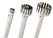
Multi-Gen 7 & 7XL Generator Probe Maintenance Steps:
Perform a lower / upper bearing check (items are identical):
- It is time to replace your lower Polytetrafluoroethylene (PTFE) bearing if...
- The inside diameter of the lower PTFE bearing fits loosely on the outside diameter of the shaft
- And/or you can wiggle and tilt the PTFE bearing
- The lower and upper PTFE bearing for all Multi-Gen Generator probes is the same.
- You will need to order part number PRO-03-11703P (6 pack of MULTI-GEN lower PTFE bearings)
- Visit our generator replacement parts page on our website
- Speak with a sales consultant at PRO Scientific, P#203-267-4600, sales@proscientific.com, and they will be happy to assist you in finding the correct replacement part for your generator.
- Click here to request return paperwork for your homogenizer and/or generator.
Dismantling and Assembly Instructions
 5mm PRO Quick Connect Generator:
The following instructions are for the assembly of only 5mm generators.
1. Insert the lower bearing into the bottom of the tube and collar assembly. Take the rotor knife and place it into the bottom of the tube and collar assembly and push the lower bearing into its proper location. The proper location is when the end of the rotor knife is flush with the bottom of the tube and collar assembly.
2. Insert the rotor shaft into the upper end of the tube and collar assembly.
3. The rotor shaft should rotate freely within the tube and collar assembly. If the rotor shaft does not rotate freely, remove the rotor shaft from the tube and collar assembly and inspect both the upper and lower bearings for any possible damage. Replace any damaged bearings.
4. Insert the rotor knife into the end of the tube and collar assembly and rotate the knife clockwise with the screwdriver tool while holding the rotor shaft. Rotor knife should be hand tight. Do not overtighten.
5. With the rotor knife attached, place the generator with the blade end down onto a flat surface. Place the PTFE washer onto the shaft. Then place the rotor shaft collar assembly on top of that. Align the set screw from the rotor shaft collar with the flat on the rotor shaft and tighten with the 5/64 hex head wrench (provided in the tool kit). Check that the generator rotates freely.
The following instructions are for the dismantling of 5mm generators ONLY
1. Unscrew the rotor knife from the bottom of the rotor shaft. Insert the 1/4" hex key (supplied in the tool kit) into the end of the rotor shaft collar and insert the screwdriver (supplied in the tool kit) into the rotor knife and turn the hex wrench counterclockwise.
2. Remove the rotor knife from the bottom of the generator tube and collar assembly.
3. Draw the rotor shaft and rotor shaft collar assembly upwards out of the tube and collar assembly. The PTFE (Polytetrafluoroethylene) washer can be removed from the rotor shaft.
4. Remove the lower bearing from the bottom of the tube and collar assembly. The lower bearing should be replaced when worn before the rotor knife starts to rub against the inside of the stator.
5. The rotor shaft collar assembly can be removed from the rotor shaft by loosening the set screw located at the side of the rotor shaft collar using the 5/64 hex wrench. (supplied in the tool kit). For convenience do not fully remove the set screw from within the rotor shaft collar assembly.
 7mm, 10mm, 20mm, and 30mm PRO Quick Connect Generators:
The following instructions are for the assembly of only 7mm, 10mm, 20mm, and 30mm generators.
- Slide the lower bearing onto the rotor shaft.
- Attach the rotor knife to the rotor shaft by screwing it together until tight in a clockwise direction
- **HAND TIGHTEN ONLY. OVER TIGHTENING OF THE ROTOR KNIFE ONTO THE ROTOR SHAFT CAN RESULT IN BREAKING OF THE ROTOR SHAFT AND/OR DISTORTING OF THE ROTOR KNIFE.**
- Insert the Rotor Shaft into the end of the tube and collar assembly. Then push the rotor knife up into the end of the tube and collar assembly until it cannot go any further. This will put the lower bearing in its proper place. The rotor shaft should stick out through the upper bearing located at the top of the tube and collar assembly.
- While pushing against the rotor knife, place the PTFE washer over the end of the rotor shaft and put the rotor collar assembly onto the rotor shaft.
- While holding the rotor knife, align the set screw on the side of the rotor shaft collar and the flat end on the rotor shaft so they are facing each other. Once lined up with one another, tighten the set screw against the flat end of the rotor shaft using the 5/64 hex wrench (supplied in the tool kit).
The following instructions are for the dismantling of only 7mm, 10mm, 20mm, and 30mm generators.
- Remove the rotor shaft collar assembly by loosening the setscrew located in the side of the rotor shaft collar from the rotor shaft using the 5/64 hex wrench (supplied in the tool kit)
- For convenience, do not fully remove the setscrew from within the rotor shaft collar assembly
- Remove the upper PTFE washer from the rotor shaft. Draw the rotor shaft downwards out of the tube and collar assembly. (If rotor shaft does not slide out, press down on the rotor shaft from the top of the generator tube and collar assembly using the 5/64 hex wrench).
- Re-attach the rotor shaft collar assembly to the flat portion of the upper shaft.
- Unscrew the rotor knife from the bottom of the rotor shaft.
- Insert the ¼” hex key (supplied in the tool kit) into the end of the rotor shaft collar and hold stationary
- Unscrew the blade in a counter-clockwise direction
- Remove the lower bearing from the end of the shaft.
- The lower bearing should be replaced when it shows signs of wear and before the rotor knife starts to come in contact with the inside of the stator.
- “HD” generator probes have a press-fit, keyed in PTFE Heavy-Duty lower bearing that may not slide out of the chamber until it begins to wear
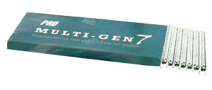
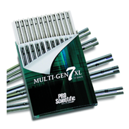
 Multi-Gen 7 and 7XL Generators:
The following instructions are for the assembly of Multi-Gen 7 & 7XL generators.
- Insert upper PTFE bearing (bearings are interchangeable) into the upper end of the generator tube-bearing, flange out.
- Place the lower PTFE bearing into the lower end of the generator tube- bearing flange out.
- Slide shaft into the lower end of the generator tube until the knife is flush with the tube, making sure the threaded end of the shaft comes through the upper PTFE bearing.
- With finger keeping knife flush with the bottom of the tube, hand-tighten drive collar.
- FINAL ASSEMBLY STEP FOR MULTI-GEN 7 ONLY: Place the screwdriver into the bottom of the generator and holding the drive collar turn the screwdriver clockwise.
- FINAL ASSEMBLY STEP FOR MULTI-GEN 7XL ONLY: Place Allen wrench across and through the open slot of the XL generator to ensure the tightness of assembly and holding drive collar turn screwdriver clockwise.
The following instructions are for the dismantling of Multi-Gen 7 & 7XL generators.
Dismantling Multi-Gen 7 Probes Only
- Insert the Allen wrench end of the screwdriver (supplied in the motor unit tool kit) across and through the open slot of the XL generator tube
- Continue with step 3 from the 7XL instruction below.
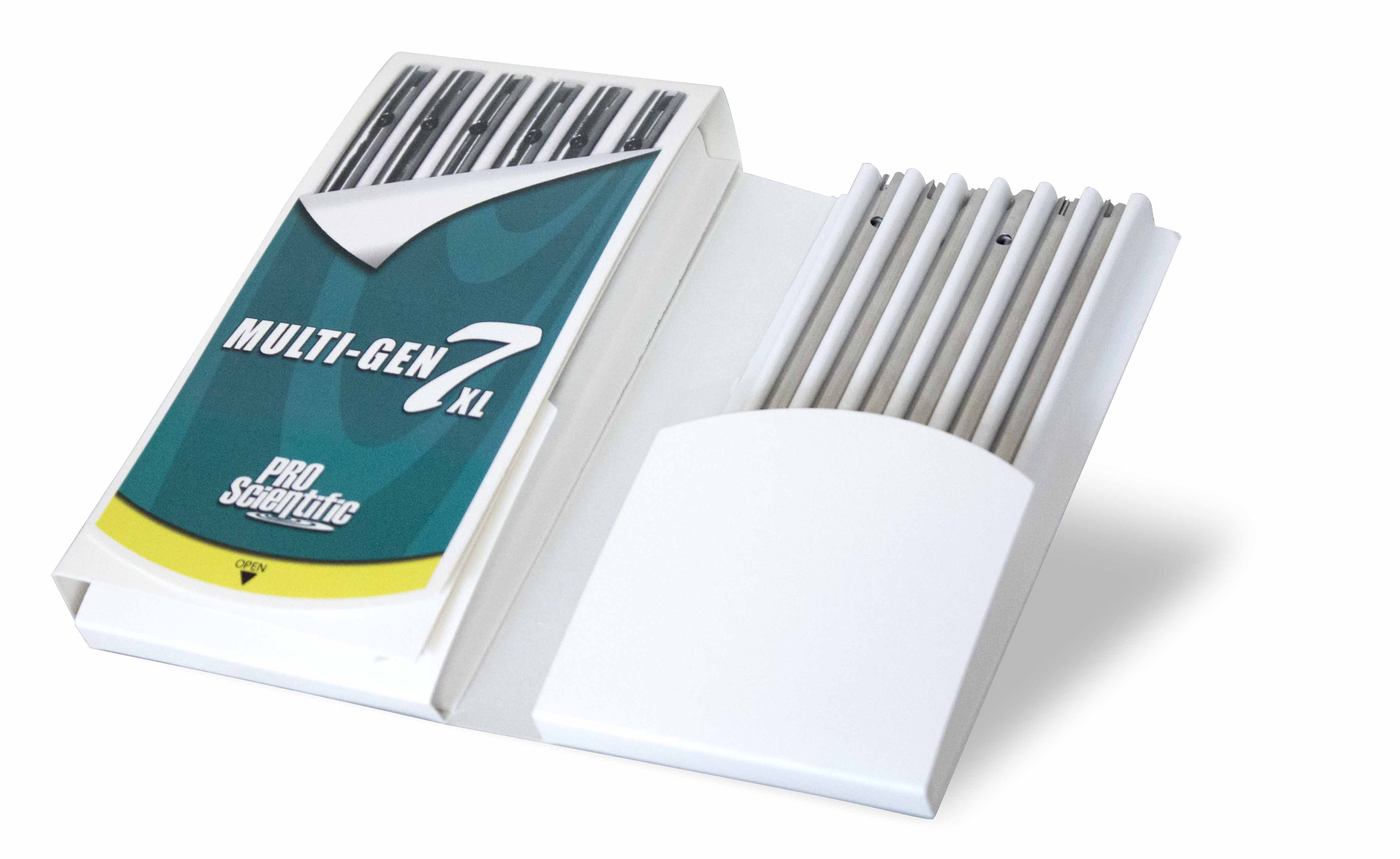
Dismantling Multi-Gen 7XL Probes
- Insert the Allen wrench end of the screwdriver (supplied in the motor unit tool kit) across and through the open slot of the XL generator tube
- Continue with step 3.
- While firmly holding the drive collar at the upper end of the generator (opposite end of the screwdriver) turn the screwdriver counterclockwise. If the drive collar is not held securely it will spin with the screwdriver, thereby not allowing the knife assembly and rotor shaft to be unscrewed from the drive collar.
- With the drive collar removed, the rotor shaft knife assembly will slide out the bottom of the generator tube.
- The upper PTFE bearing can now be removed from the upper end of the generator tube.
- The lower PTFE bearing can now be removed from the lower end of the generator tube.
- Multi-Gen parts can now be placed on a tray and autoclaved as necessary.
Cleaning of PRO Quick Connect Generator Probes and Multi-Gen 7 / 7XL's.
- Immediately after you have finished working with the generator, the generator must be cleaned so that the substance residues do not stick to the rotor and stator and allow small bacterial cultures to form in undesirable places.
- For this purpose, the generator should be run in a solvent, which dissolves the substance residue and does not harm the components. The rotor and stator are cleaned as the solvent is pumped through the generator.
- Please ensure that all cleaning processes are compatible with 316SS and PTFE.
- For a more thorough cleaning it is recommended that your generator be disassembled and cleaned via one of the following processes;
- Chemical process - Germicidal solutions (formalin, phenol, alcohol, etc.) can disinfect in most cases.
- Residues of the germicide must subsequently be removed with sterilized water.
- Please ensure that all chemical processes are compatible with 316SS and PTFE.
- Sterilizing by humid heat – This means sterilizing with steam at a pressure of 2 bar above the atmosphere and a temperature of 120°C.
- PRO Generators are heat resistant up to 390° F / 198° C.
- Sterilizing by hot air - Hot air sterilization is normally carried out at 160 to 190°C.
- PRO Generators are heat resistant up to 390° F / 198° C
- Flaming - This method can be used, however, it is only effective on external surfaces.
- PRO Generators are heat resistant up to 390° F / 198° C
- Chemical process - Germicidal solutions (formalin, phenol, alcohol, etc.) can disinfect in most cases.
For additional PRO Homogenizer Motor Unit Maintenance Click Here
Click here to request return paperwork for your homogenizer and/or generator.
![]()
Resources
Related Links
- Download our PRO Generator Probe Quick Care Guide
- Learn more about the technology behind rotor-stator homogenizers
- Learn more about PRO Homogenizing applications
- Learn more about PRO Scientific Homogenizer Package Kits
- View all of our PRO Homogenizer Units
- Request a quote
- View information on homogenizer maintenance